Maximise the efficiency of your patch antenna using simulation
When it comes to designing an antenna, one of the primary objectives is to ensure optimum signal transmission.
To achieve this, it’s essential to optimise the antenna’s matching to maximise the radiation of energy from the feed source to the outside.
In this article, we show you how to optimise the matching of a patch antenna using our new simulation software, CAPITOLE RF.
Sommaire / Contents
First simulation
Initially, we carry out an initial simulation without seeking to optimise antenna matching.

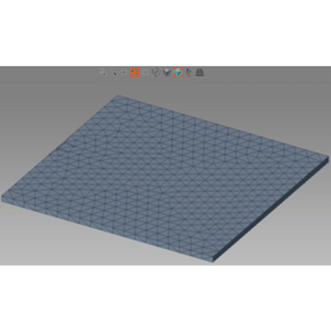
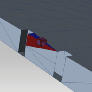
Meshing
The mesh is created automatically by CAPITOLE.
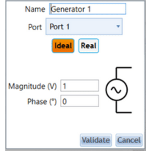
Power supply
The power supply consists of a voltage source generator positioned directly at the end of the power supply line.
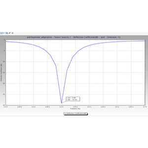
Calculation of the reflection coefficient
In this non-optimised configuration, a calculation is carried out using a solver based on the method of moments to determine the reflection coefficient.
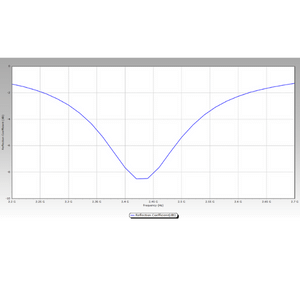
The antenna designed to operate around 2.4 GHz has a reflection coefficient of around -9dB, which is not optimal.
To improve the antenna’s matching performance, a matching circuit was added, consisting of a schematic including a 1.4 pF capacitor in parallel.

Capitole’s “ad matching networks” function was used to achieve this improvement.
Once the calculation has been run again with this new configuration, the result shows a curve with a much lower reflection coefficient in the antenna’s operating band.
At 2.4 GHz, we can see that the reflection coefficient is now close to -30 dB, which confirms that the antenna is much better adapted.
Conclusion
Optimising the matching of a patch antenna through simulation is an essential process for ensuring efficient signal transmission.
With our simulation software, you can explore a wide range of configurations and parameters to improve the performance of your antenna.
Using CAPITOLE RF will enable you to create high-performance patch antennas capable of meeting the most demanding communication requirements.